allowance called a layer of material removed during the machining of a workpiece to achieve the required accuracy and quality of the machined surface.
There are intermediate allowances ( Zi) and common ( ZO).
Intermediate allowance (allowance for a given operation or transition) - a layer of metal that must be removed during a given operation or transition. The intermediate allowance is defined as the difference in the dimensions of the workpiece obtained at the adjacent previous transition. When designating allowances, the following indices are used: ( i-1) – index for the previous transition; i– index for the transition being performed.

ALLOWANCES FOR MECHANICAL PROCESSING
Intermediate allowances for external and internal surfaces of revolution (see figure) are calculated using the following formulas:
2 , 2 ,
Where Zi- allowance to the side.
Allowances are measured along the normal to the machined surface. They can be asymmetrical(on one side) in the manufacture of prismatic parts and symmetrical(on both sides) most often on the diameter when processing bodies of revolution.

ALLOWANCES FOR MECHANICAL PROCESSING
General allowance is equal to the sum of intermediate allowances along the entire technological route of machining a given surface
The total allowance is defined as the difference between the dimensions of the workpiece and the finished part. It depends on a number of factors: the type of production, the dimensions and structural forms of the workpiece, its properties, its material, the type of workpiece (forging, casting), its rigidity, the thickness of the defective surface layer, the condition of the equipment on which processing is carried out.

ALLOWANCES FOR MECHANICAL PROCESSING
Properly selected allowance ensures stable operation of the equipment while achieving high product quality, as well as the minimum cost of production.
Allowances should be assigned optimal. Overestimated allowances lead to excessive material consumption, an increase in the laboriousness of machining, an increase in the operating costs of machining (tool consumption, electricity, etc.). Insufficient allowances can prevent the correction of errors from previous processing and obtaining the necessary accuracy and roughness of the machined surface in the operation being performed.
EXPERIMENTAL-STATISTICAL METHOD FOR DETERMINING ALLOWANCES
In mechanical engineering, two methods for determining allowances are used: experimental-statistical and computational-analytical.
Using experimental-statistical method general and intermediate allowances are assigned according to tables, which are compiled on the basis of generalization and systematization of production data of advanced factories. The main advantages of this method can be considered time savings for determining the allowance. It allows you to determine the dimensions of the workpieces before the development of TP.

DISADVANTAGES OF THE EXPERIMENTAL-STATISTICAL METHOD FOR DETERMINING ALLOWANCES
The disadvantages of the experimental-statistical method are that allowances are assigned without taking into account the specific conditions for constructing technological processes, for example, general allowances are assigned without taking into account the workpiece installation scheme and errors of previous processing.
The experimental-statistical method for determining the allowance does not take into account the features of the TP, the recommended allowances are overestimated. Tables for the selection of allowances can be used in single and small-scale production, in the manufacture of small, inexpensive parts, when route technological processes are being developed.

CALCULATION AND ANALYTICAL METHOD FOR DETERMINING ALLOWANCES
With this method, the value of the allowance is determined by a differentiated calculation by elements.
The calculation-analytical method provides for the calculation of allowances for all sequentially performed technological operations for processing a given surface of a part, their summation to determine the total allowance, and the calculation of intermediate dimensions of the workpiece.
The calculated value is the minimum intermediate allowance sufficient to eliminate the processing errors and surface layer defects obtained in the previous operation at the operation being performed, and to compensate for the errors that occur in the operation being performed.

When calculating the minimum intermediate allowance, the following elements are taken into account:
1) the height of microroughnesses obtained at the previous transition;
2) condition and depth hi-1 the surface layer of the workpiece as a result of the previous transition;
3) spatial deviations in the location of the machined surface relative to the workpiece bases;
4) installation error when performing this transition.

Calculation of the minimum intermediate allowance
Surface roughness and depth of the surface layer hi-1 depends on the cutting mode, the quality of the material being processed and other factors.
Surface layer hi-1 , formed as a result of the previous transition, is completely or partially removed at the transition being executed. For example, when making forgings, a decarburized layer up to 0.5 mm is formed, which should be removed completely, since this layer is defective. It is necessary to completely remove the surface layer formed during the casting of a workpiece from gray cast iron at the very first technological transition. This layer of 1…2 mm consists of pearlite crust with inclusions of foundry sand.

Calculation of the minimum intermediate allowance
Spatial deviations - these are deviations, ri-1, which are characterized by an error in the location of the machined surface relative to the base surfaces of the workpiece (deviations from the alignment of the outer surface of rotation and the surface of the hole for workpieces such as bushings and disks; bending of the stepped shaft workpiece; convexity and concavity of the planes; deviation from parallelism to be processed plane of the body and the reference plane; deviation from perpendicularity of the end surface to the axis of the hole) .

Calculation of the minimum intermediate allowance
Component The minimum intermediate allowance is also the error in the installation of workpieces on the transition being performed.
Installation error characterized by a displacement or rotation of the surface to be processed relative to the bases, therefore this value must be compensated by a corresponding increase in the allowance.

Calculation of the minimum intermediate allowance
For example, when machining a bushing according to the outer diameter, when installing the base hole on a mandrel with a gap, the workpiece receives an offset
Where - guaranteed clearance between the workpiece hole and the mandrel; T1- admission to the manufacture of the mandrel; T2- tolerance for the manufacture of the base hole; T3- mandrel wear tolerance.

Calculation of the minimum intermediate allowance
Summing up the values, and, we get the minimum allowance for the technological transition.
Consider the methods of summing the components. When processing planes, the vectors and are summed arithmetically, since they are collinear (parallel) and directed perpendicular to the surface to be machined. Therefore, when processing a plane, the calculation formula for the minimum allowance has the form

Calculation of the minimum intermediate allowance
When processing two opposite planes with the same methods, the allowance on two sides will be
When processing surfaces of revolution, vectors i-1 And i can take any angular position and therefore their summation should be performed according to the rule square root.
Therefore, the allowance for the diameter when machining the outer and inner surfaces of rotation will be

Calculation of the minimum intermediate allowance
The values of the components of the minimum allowance are given in the reference literature. The specific values of these components depend on the accuracy of the execution of the previous and ongoing transitions, the accuracy of setting the workpiece on the transition being performed, the material of the workpiece, and other factors.

Calculation of the minimum intermediate allowance
When analyzing specific transitions, some components from the general calculation formula can be excluded.
So, when turning the cylindrical surface of the workpiece, installed in the centers, the error can be taken equal to zero and, therefore,

Calculation of the minimum intermediate allowance
When grinding workpieces after heat treatment, the surface layer must be preserved as far as possible, therefore, the term must be excluded from the calculation formula, i.e.
When deploying with a floating sweep and pulling holes, displacements and axis slip are not eliminated, and there are no installation errors in this case. That's why

Calculation of the minimum intermediate allowance
When superfinishing and polishing a cylindrical surface, when only its roughness decreases, the allowance is determined only by the height of the microroughness of the treated surface, i.e.
Therefore, when calculating the minimum allowance, specific processing conditions should be taken into account. Depending on these conditions, some terms are not taken into account, which allows you to reduce the allowance and reduce processing costs.

Calculation of the minimum intermediate allowance
The positive part of the tolerance for the workpiece for the shaft and the negative part for the hole are not included in the total allowance, but should be taken into account when determining the cutting conditions during processing.
Knowing the minimum interoperational allowance, you can calculate its maximum value
Where T i-1 , T i- tolerances for the size of the surface, established respectively for the previous and ongoing technological transition.


Calculation of workpiece dimensions during machining

Calculation of workpiece dimensions during machining
For shafts Dimax = Di-1max - 2Zimin - TDi-1;
Dimin = Di-1min– 2Zimin – TDi .
Schemes for the formation of intermediate sizes during the processing of external and internal cylindrical surfaces are shown in the figures. Using the relationship between interoperational processing allowances and tolerance fields set on intermediate sizes, you can calculate the limiting dimensions of the workpiece when performing any technological transition using the following relationships.

Calculation of workpiece dimensions during machining
Hole workpiece limits
Dimax = Di-1max + 2Zimin + TDi ;
Dimin = Di-1min + 2Zimin + TDi-1 .
Allowances for different workpieces for various types of machining are given in GOST, factory regulatory materials and reference books.
Operational allowances for machining (per diameter) lie within the following limits: for rough turning of a rolled workpiece with a diameter of up to 120 mm - from 1 to 2.5 mm, for stamping blanks - from 1.5 to 3 mm; with fine turning after rough turning - from 0.5 to 1 mm; for external grinding in the centers - from 0.2 to 0.5 mm.

EXAMPLE OF CALCULATION OF ALLOWANCES
Calculate machining allowances and intermediate limit dimensions for the hole Ø50H7 of the part shown in the figure.

EXAMPLE OF CALCULATION OF ALLOWANCES
The blank is a casting of the 1st accuracy class.
Technological processing route:
rough reaming;
fine reaming;
clean deployment.
The workpiece is based in the fixture along the machined end, perpendicular to the axis of the hole Ø50H7, and two holes Ø18H7.

EXAMPLE OF CALCULATION OF ALLOWANCES
The calculation of the allowances for processing holes Ø50Н7 will be carried out in a table in which the technological route of processing the hole and the values of the elements of the allowance included in the formula are recorded
The calculation procedure and reference data for this calculation are given in the books:
1. Reference technologist-machine builder. In 2 vols. Vol. 1 / Ed. A.G. Kosilova and R.K. Meshcheryakov. - M.: Mashinostroenie, 1986. - 656 p.
2. Gorbatsevich A.F. Course design for engineering technology /A.F.Gorbatsevich, V.A.Shkred. - Mn.: Vysh. school, 1983. - 256 p.

EXAMPLE OF CALCULATION OF ALLOWANCES

EXAMPLE OF CALCULATION OF ALLOWANCES
According to table 6, p. 182 for cast iron castings of the 1st accuracy class, the total value (Rz + h) is 400 microns.
After the first technological transition for parts made of gray cast iron, the term h is excluded from the formula for the minimum allowance. Therefore, we are not interested in the values of the parameter h obtained in roughing and finishing reaming, as well as reaming, and we will take into account only the parameter Rz.
According to table 3, p. 92 , with finishing reaming in the worst case Ra=1.25 µm or Rz ≈ 4Ra = 5 µm (this roughness is given on the detail drawing). When finishing countersinking, the worst value of Ra is 3.2 µm (Rz=4Ra=12.8 µm), we take Rz=13 µm. With rough countersinking Ra=6.3 µm, we take Rz=25 µm. We put these values in the table.

EXAMPLE OF CALCULATION OF ALLOWANCES
Let's find the total deviations of the location and shape of the surface of the hole Ø50H7.
For the workpiece, the total value of the spatial deviation is determined by the formula
where kor=kL – deviation of the flat surface from the plane (warping);
cm - hole displacement,
L is the hole length, mm.
We will take into account the buckling of the hole in the axial and diametral directions.

EXAMPLE OF CALCULATION OF ALLOWANCES
According to Table 8, p.183, the specific warping k of castings of body parts is 0.3…1.5 µm per 1 mm of length. We take k=0.9 µm and find
Hole displacement cm is taken equal to the size tolerance from the axis of the hole being machined to the technological base - the axis of the hole Ø18H7, i.e. 90 size tolerance (see drawing) of 0.4 mm. Hence,

EXAMPLE OF CALCULATION OF ALLOWANCES
The fixing error is taken equal to zero, since the fixing forces are perpendicular to the size being performed. Therefore, the installation error for rough reaming is 1 = 448 µm.
The workpiece installation error during rough reaming is determined by the basing error that occurs due to the deviation from the perpendicularity of the reference end of the workpiece axis. The processing of the reference end was carried out earlier. Its non-perpendicularity to the axis of the workpiece is 0.6 tolerance for size 280, i.e. 0.6x200=120 µm. Then the largest basing error at length 280 will be
EXAMPLE OF CALCULATION OF ALLOWANCES
Residual error after rough reaming, according to the recommendations,
2 = 0.04 1 = 0.04 448 = 18 microns.
Residual error after fine countersinking for reaming
3 = 0.005 448 = 2 µm.
Using the data recorded in the table, we calculate the minimum allowance values according to the formula

EXAMPLE OF CALCULATION OF ALLOWANCES
Using the data recorded in the table, we calculate the minimum allowance values.
Minimum allowance for rough reaming
for fine reaming -
and for clean deployment -

EXAMPLE OF CALCULATION OF ALLOWANCES
Let us determine the calculated dimensions dр, starting from the final (drawing) size, by successively subtracting the calculated allowance of each technological transition.
After finishing reaming dр3=50.025 mm;
for fine reaming dр2=50.025 - 0.030 = 49.995 mm;
for rough reaming dр1=49.995 - 0.102 = 49.893 mm;
for the workpiece dр0=49.893 – 2.106 = 47.787 mm.

EXAMPLE OF CALCULATION OF ALLOWANCES
The tolerance values of the obtained dimensions are taken from the tables in accordance with the quality of accuracy of this type of processing.
For fine reaming Td3 = 25 µm.
For fine reaming after roughing, accuracy grade 8, according to table 5, p. 11 , Td2 = 39 μm.
For rough reaming, accuracy grade 10, Td1 = 100 µm.
For a workpiece, the tolerance for a hole in a casting of the 1st accuracy class is Td0 = 400 µm - Table 3, p. 120 .

EXAMPLE OF CALCULATION OF ALLOWANCES
The values of dmax are obtained from the calculated dimensions, rounded up to the accuracy of the tolerance of the corresponding transition.
The dimensions dmin are determined from the largest limit dimensions by subtracting the tolerances of the corresponding transitions:
For finishing deployment dmax3 = 50.03; dmin3 = 50.005;
for fine reaming dmax2 = 50.00; dmin2 = 49.961;
for rough reaming dmax1 = 49.89; dmin1 = 49.79;
for the workpiece dmax0 = 47.79; dmin0 = 47.39.

EXAMPLE OF CALCULATION OF ALLOWANCES
The minimum limit values of the allowances 2Zmin are equal to the difference between the largest limit sizes of the performed and previous transition, and the maximum limit values 2Zmax are the difference of the smallest limit sizes.
Choice of processing route
Selection of installation bases
The choice of mounting bases is carried out in order to outline the procedure for changing the bases (if necessary) when performing the technological process of machining the part. The initial data when choosing bases are:
Working drawing of a part with predetermined dimensions;
Specifications for its manufacture;
Type of workpiece;
Desired degree of process automation.
The main provisions for the choice of bases and requirements for base surfaces are discussed in Section 1. However, when choosing installation bases, it is useful to keep in mind the two principles discussed earlier, i.e. the principle of alignment of bases to avoid the error of basing and the principle of constancy of bases, which helps to increase the accuracy of the relative position of the surfaces of the part.
The purpose of establishing a machining route and machining method is to provide the most rational machining process for a part. The route indicates the sequence of technological operations, and for each operation, the processing method, the equipment used, the device used, the working and measuring tools, processing modes, time standards, work qualifications are established.
The plan should provide for the division of the technological process of processing into its constituent parts: operations, installations, positions, transitions, passages, and, if necessary, techniques.
The calculation of processing allowances includes:
Factors determining the amount of the minimum allowance;
Methods for determining allowances.
Any workpiece, if it is further subjected to machining, is made with an allowance. What is meant by machining allowance? A machining allowance is understood as a layer of material that must be removed during machining in order to obtain a given dimensional accuracy, shape and surface roughness of the finished part. Based on the definition, it follows that surfaces that are not processed do not have allowances. The value of the total allowance for the machined surface is determined by the difference between the dimensions of the workpiece and the finished part.
There are general allowances and interoperational allowances. The general allowance is a layer of material removed during the entire processing, and the interoperation allowance is in one operation. It is easy to find out that the total processing allowance will be determined by the sum of the interoperational allowances.
According to the location of the allowances, symmetrical and asymmetrical ones are distinguished. Symmetrical allowances can be on the outer and inner surfaces of the bodies of revolution, as well as on opposite flat surfaces while simultaneously processing them. An asymmetric arrangement of allowances is observed with one-sided surface treatment, however, the possibility is not ruled out when processing the above-mentioned surfaces.
The machining allowance must be optimal, i.e. it must provide the specified accuracy of machining and at the same time have the lowest material consumption, i.e. Excessive allowances cause measurement costs in the manufacture of the part, and underestimated allowances, on the contrary, do not meet the established requirements for roughness, surface layer quality, material and dimensional accuracy.
Thus, the following number of factors influence the value of machining allowances and tolerances on the dimensions of workpieces:
workpiece material;
The configuration and dimensions of the workpiece;
Type of workpiece and method of its manufacture;
Machining requirements;
Specifications regarding the quality and class of surface roughness and dimensional accuracy of the part.
Currently, there are two methods for determining allowances for machining parts: experimental-statistical, or more often it is called tabular and calculation-analytical.
The essence of the tabular method for determining allowances lies in the fact that under production conditions, the allowances are set on the basis of experience, using practical data depending on the mass and overall dimensions of the parts, structural shapes and dimensions, the required accuracy and the roughness class of the treated surface. Based on these statistics, normative tables of allowances are compiled, which are used for their production or industry. The value of the tabular allowance for the work surface of the same name is greater than the allowance determined by the calculation and analytical method, i.e. a certain percentage of margin is given to satisfy all requirements for the surface to be machined.
The calculation and analytical method for determining allowances was proposed by prof. V.M. Forged. Its value is determined by calculation according to the formulas:
For a symmetrical allowance - for the diameter of the outer and inner surfaces of the bodies of revolution:
Symmetrical allowance for both opposite parallel
flat surfaces:
Asymmetric allowance - on one of the opposite parallels
molded flat surfaces:
where Z is the minimum allowance for the transition to be performed
R a is the height of microroughnesses;
T a is the thickness of the defective surface layer remaining
from previous processing;
ρ a - the total value of spatial deviations;
ε in - the error in the installation of workpieces when performing
operations.
The index "a" at the terms of the allowance shows that its value must be taken from the previous transition or processing, and "c" - from the transition being performed. The coefficient "2" in the formulas means that the allowance is accepted for the diameter or for both sides.
The maximum allowance is determined by the formula
where δ a is the size tolerance obtained on the previous
transition;
δ in - tolerance on the size obtained on the performed
transition, and the accuracy class that the processing gives
at the technological transition.
Determination of the original forging index.
Factors that determine the original workpiece index, which is the key to finding overall allowances and tolerances for forgings:
1. Estimated weight of the forging M p.r. , kg.
2. Steel group MI, M2, M3.
3. Degree of difficulty C1, C2, C3, C4.
4. Accuracy class. for stamping in open dies T4 and T5.
Here is the formula for determining the estimated mass of the forging.
M p.r. = M d K p,
where M d is the mass of the part (determined from the drawing), kg;
K p - consumption coefficient. For round parts in plan (hubs, gears, etc.) - K p \u003d 1.5 - 1.8.
Let's take K p \u003d 1.7. Then M p.r. \u003d 2.49 1.7 \u003d 4.23 kg.
Steel groups are determined by the percentage of carbon: M1 - up to 0.35%; M2 - (0.35-0.65)%; M3 - 0.65% or more. In our case, for steel 30, the steel group will be M1.
The degree of complexity is determined by finding the ratio of the volume V p - forging to the volume V Ф - an elementary geometric figure into which the forging fits. Or you can take the ratio of the calculated mass of the forging M p.r. to the mass of the elementary geometric figure M f. For our case, this will be a cylinder. The overall dimensions of the part (D max and H) are required in the calculation. We will determine the degree of complexity by the mass ratios. The approximate dimensions of the elements of the figure are determined by an increase of 1.05 times.
The mass of the elementary figure will be
The degree of difficulty will
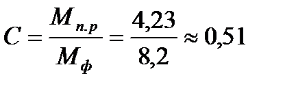
This corresponds to C2 (range 0.32...0.63).
According to the diagram, we determine:
For M p.r. \u003d 4.23 kg (3.2-5.6), Ml go horizontally to Cl, then go down the slope to the vertical C2 and again move horizontally to T4 and again go down the slope to the vertical T5 and go horizontally to the index 14.
Determination of allowances for machining.
In the tables, allowances are given per side. The allowance will be determined by:
1. Initial index.
2. The size that binds the surfaces.
3. Surface roughness of the finished part.
4. By the method of forming surfaces connected by a linear dimension: in different halves of the stamp or in one (when stamping on presses and hammers). If they are formed in different halves of the stamp, then the size is selected in the "Part THICKNESS" line. If it is formed in one half, then the size is selected in the line "LENGTH, WIDTH, DIAMETER, DEPTH, and HEIGHT of the part."
These same factors, except for the third one, will also determine the amount of deviation allowed for dimensions.
The total allowance for machining includes the main and additional allowances. The definition of the main allowances is reflected in table. 2.1. Additional allowances (Table 2.2) take into account the displacement of forgings, curvature, deviation from flatness and straightness. The definition of the dimensions of the original workpiece is given in table. 2.3
Table 2.1 - Determination of the main allowances
| Surface (blanks) | Thickness, mm | Height, diameter, mm | Roughness, Ra | Main allowance, mm | |
| 1 | 75 | - | 3,2 | 2,5 | |
| 7 | 3,2 | 2,5 | |||
| 5 | - | 43 | 12,5 | 1,7 | |
| 7 | 3,2 | 2,0 | |||
| 2-2 | - | Ø120 | 12,5 | 1,9 | |
| 6-6 | - | Ø100 | 1,6 | 2,0 | |
| 4-4 | - | Ø80 | 1,6 | 2,0 | |
Table 2.2 - Determination of total allowances and estimated dimensions of the original workpiece
| Pov. | Size mm | Allowances Z, mm | General allowances | Estimated size, mm | ||
| Basic | Additional | To the side, Z o | Per diameter, 2Z o | |||
| 2-2 | 120 | 1,9 | 0,3 | 2,2 | 4,4 | 120+4,4 =124,4 |
| 6-6 | 100 | 2,0 | 0,3 | 2,3 | 4,6 | 100+4,6= 104,6 |
| 4-4 | 80 | 2,0 | 0,3 | 2,3 | 4,6 | 80-4,6=75,4 |
| 1 | 75 | 2,5 | 0,5 | 3,0 | - | 75+6=81* |
| 7 | 2,5 | 0,5 | 3,0 | - | ||
| 5 | 43 | 1,7 | 0,5 | 2,2 | - | 43+3-2,2=43,8* |
| 7 | 2,5 | 0,5 | 3,0 | |||
Table 2.3 - Appointment of tolerances, limit deviations and determination of the dimensions of the original workpiece.
| Estimated size, mm | Tolerance, T, mm | VO, mm | BUT, mm | Accepted size, mm |
| Ø124.4 | 3,2 | +2,1 | -1,1 | Ø 124.4 |
| Ø 104.6 | 3,2 | +2,1 | -1,1 | Ø 104.6 |
| Ø 75.4 | 2,8 | +1,0 | -1,8 | Ø 75.4 |
| 81 | 3,2 | +2,1 | -1,1 | 81 * |
| 43,8 | 2,8 | +1,8 | -1,0 | 43,8 * |
| * To be determined by dimensional analysis |
According to the table, we determine the initial index of the forging. For steel group M1, degree of complexity C2 and accuracy class T5, taking into account the calculated mass of the forging, the initial index will be 14.
According to the table for the original index 14, taking into account the size intervals that L1 and L2 fall into, taking into account the type of size (thickness or height), the tolerances for these dimensions will be TL1=3.2 () and TL2=2.8 ().
When defining tolerances, the type of dimension, thickness or height is also taken into account. So the dimension L1 refers to the thickness, and the dimension L2 refers to the height.
2.3 Development of route technological process of processing
details and equipment selection
The development of a route technological process for the machining of a workpiece is the basis of the entire course project. The organization of production and further technical and economic calculations of the course project largely depend on the correctness and completeness of the development of the route technological process.
In the technological part of the course project, it is necessary to give an analysis and justification of the developed technological process. First of all, it is necessary to select all the operations,
The concept of allowances, operating dimensions and permissible deviations on them. Influence of allowances on the efficiency of the technological process. Factors affecting the amount of allowance
The original workpiece differs from the part in that allowances are provided on all machined surfaces - layers of material to be removed from the surface of the workpiece during processing to obtain the specified accuracy and roughness. The material left in the recesses, grooves and holes of castings and forgings forms an overlap, which is also removed during processing. An overlap is also a layer of rolled material that exceeds the dimensions of the workpiece, taking into account the processing allowance. The overlap is removed, as a rule, in two passes (60 ... 70% - the first; 40 ... 30% - the second).
Allowances are divided into general (operational) - removed during the entire processing process and interoperational (intermediate), removed during individual operations. The interoperational allowance is determined by the difference in the dimensions of the workpiece obtained on the adjacent previous and performed transitions.
The total allowance is equal to the sum of interoperational allowances for all technological operations.
Allowances can be symmetrical (for bodies of revolution) and asymmetric - (prismatic parts).
There are nominal, minimum and maximum allowance.
Minimum allowance, i.e. the smallest layer of metal removed during processing is the difference between the smallest size of the workpiece and the smallest size after performing this transition.
The maximum allowance is equal to the nominal allowance minus the tolerance for this transition.
Nominal allowance - the difference between the nominal dimensions of the surface after the previous and after this transition.
The maximum allowance is the difference between the smallest size of the surface after the execution of the previous transition and its smallest size after the execution of this transition.
There are regulatory data, summing which you can get the value of the minimum allowance.
There are also GOST for the values of general allowances for the processing of castings and forgings. When assessing the value of the total allowance, factors are taken into account:
1) size and structural forms;
2) material and method of obtaining the workpiece;
3) the size of the defective layer;
4) installation error;
5) the degree of deformation.
It is important that the machining allowances are as small as possible in order to save metal, time, etc. To do this, in order to limit the values of intermediate allowances, technological tolerances are assigned to individual transitions.
Usually, technological intermediate tolerances for the male surface (shaft journal) are assigned as a minus, and for the female (holes) - as a plus. In any case, the intermediate tolerance is directed to the metal body.
Minimum allowance - the minimum required thickness of the material layer to perform this operation. It is the initial value when calculating allowances.
A tolerance is set on the allowance, which is the difference between the largest and smallest allowance values. The values of allowances and tolerances determine the intermediate (operational) dimensions. Determination of machining allowances consists of two main stages - determination of the machining allowances in accordance with the technological transitions of the technological process and determination of the dimensions of the workpiece, in accordance with the technical requirements of the working drawing. In this case, the dimensions of the workpiece (or the dimensions of the semi-finished product made from the starting material) are determined by summing up the processing allowances assigned for individual operations and transitions in the technological process.
Machining allowances are determined by two methods:
1) experimental-statistical- in which the values of general and intermediate allowances are determined from reference tables compiled on the basis of a generalization of production experience. The disadvantage of the method is that it does not take into account the specific conditions for constructing the technological process. The resulting allowances, as a rule, are overestimated, as they are guided by the complete absence of marriage;
2) calculation and analytical method (Professor V.M. Kovan), according to which intermediate allowance should be such that when it is removed, processing errors and surface layer defects obtained at the previous transition, as well as installation errors at this transition, are eliminated. The basis of the method is the determination of min Z.
The effect of the size of the allowance on the economics of the machining process is very large, since the larger the allowance, the greater the number of strokes required to remove the corresponding layer of metal, which leads to an increase in the complexity of the process, energy consumption, wear of the cutting tool and increases the waste of metal that turns into chips. Overestimated allowances lead to an increase in the fleet of equipment and production areas required for its placement. The size of the allowance is ensured by the accuracy of manufacturing blanks, however, increasing the requirements for accuracy in some cases also increases the cost of their manufacture in blank shops, so the allowance should be chosen optimal, i.e., ensuring the quality of the machined surface at the lowest cost of processing in mechanical and blank shops.